Blog | WatchNews
top of page

Challenges in Making an Art Deco Timepiece

- By David R. Bailey (AUS) 07/01/20

Lacquered art deco shelf clock with bronzed figures of two elephants on either side and a mouse sitting on top
Figure 1. The subject clock.

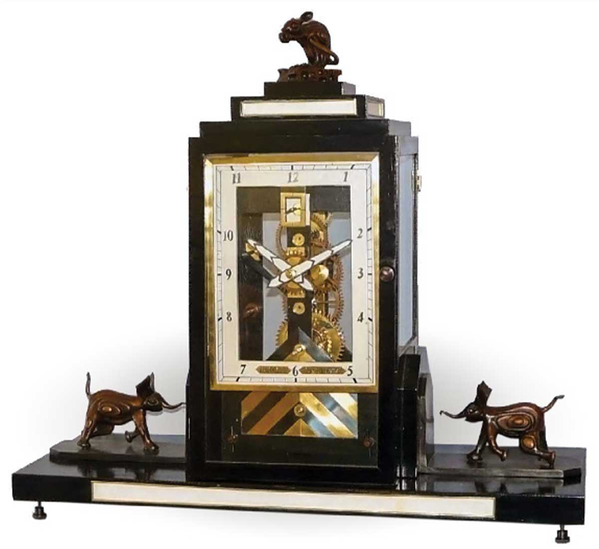
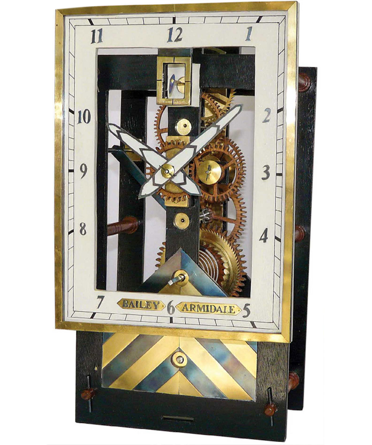
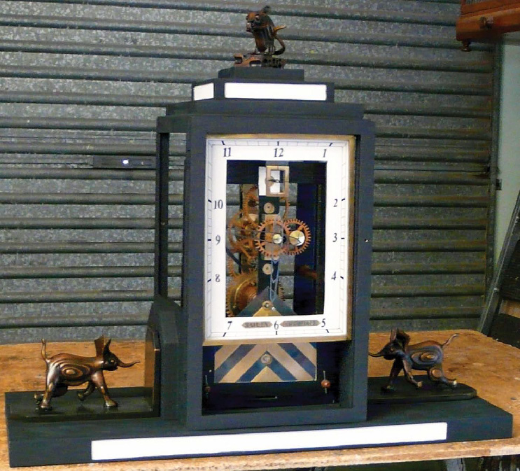
This article describes the design and creation of an 8-day Art Deco-style clock (Figure 1). The clock is spring-driven and is of hybrid construction with wheels and pinions of both wood and metal.

Introduction

I am a home-craft woodworker. During the past 35 years I have made 14 wooden-wheel clocks. My workshop is modest, but I have a good range of hand tools and a small metal turning lathe (Figure 2). Seven of the clocks I have made are of my own design. Much of my inspiration comes from early American and Black Forest wooden-wheel clocks, but in the case of this clock I decided to make it in the Art Deco style.

Before starting a clock, I form a mental picture of what features I would like the clock to have. Usually the clock will include something that I have not done before. Because a clock can take many months to create, I will not start unless I am reasonably confident that I am able to bring it to completion. With a new design there is no guarantee of success, and problems often occur along the way. These can take weeks to resolve, and occasionally no solution can be found. In this circumstance the clock could become a lifeless unfinished object, or a design compromise may be possible that will rescue the project. The latter was the case with my Art Deco clock.

An orderly workshop with many tools and several work shelves
Figure 2. The author’s home workshop.
A white modern electric wheel cutting machine roughly the size of a sewing machine
Figure 3. The author’s wheel cutting setup.

Original Design

Initially I decided on the following features:
  • Eight-day spring-driven skeleton clock with fusee and maintaining power
  • Verge and balance wheel escapement
  • Oscillation frequency of the balance wheel to be controlled by a helical spring
  • A pinwheel engaging with the verge pallets to turn once each minute and to carry a second hand
  • A pinwheel with 27 pins; thus the balance beats 54 times each minute
  • The lower end of the verge staff to pivot on a synthetic sapphire endstone
  • Pinions meshing with the great wheel and intermediate wheel to be cut from steel, and other pinions to be cut from solid Australian blackwood (Acacia melanoxylon)
  • Wheels to be made from Australian blackwood, three-ply glued with epoxy adhesive (Araldite)
  • Steel pivots to turn in brass strips inlaid into the insides of the plates
  • A rectangular dial and a movement housed in an Art Deco-style case

Making the Movement

My first step in making the movement was to calculate the tooth counts needed for the gear train. The finest tooth spacing that I can cut in wood is about 3.4 mm (0.134"), and this determined the size of some wheels and pinions (Figure 3).1 A description of how I cut wheel teeth can be found in a previous issue of the Watch & Clock Bulletin.2 After cutting the wooden wheels and pinions I cut the two steel pinions by hand, using the methods described by Penman.3 The skeletonized plates were made from 6 mm (¼") commercial plywood. The wood behind each pivot position was drilled out to give freedom for the pivots to turn without interference. Next, strips of 2.5-mm (1/10")–thick brass were inlaid and glued with epoxy adhesive into the insides of the two plates to take the pivot holes. Six 12.5-mm (½")–diameter Australian blackwood pillars were mortised and glued into the back plate and pinned at the front plate.

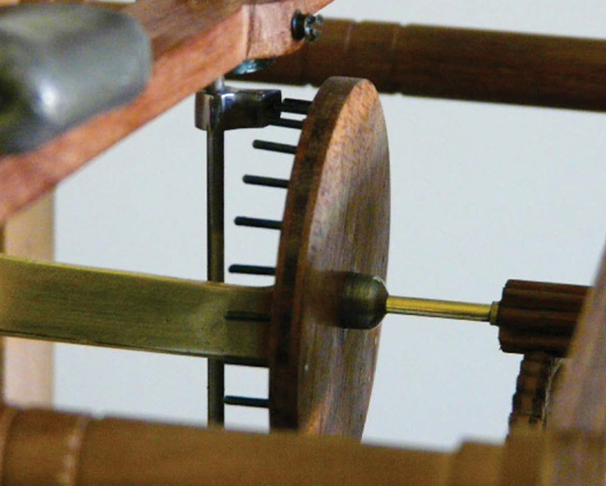
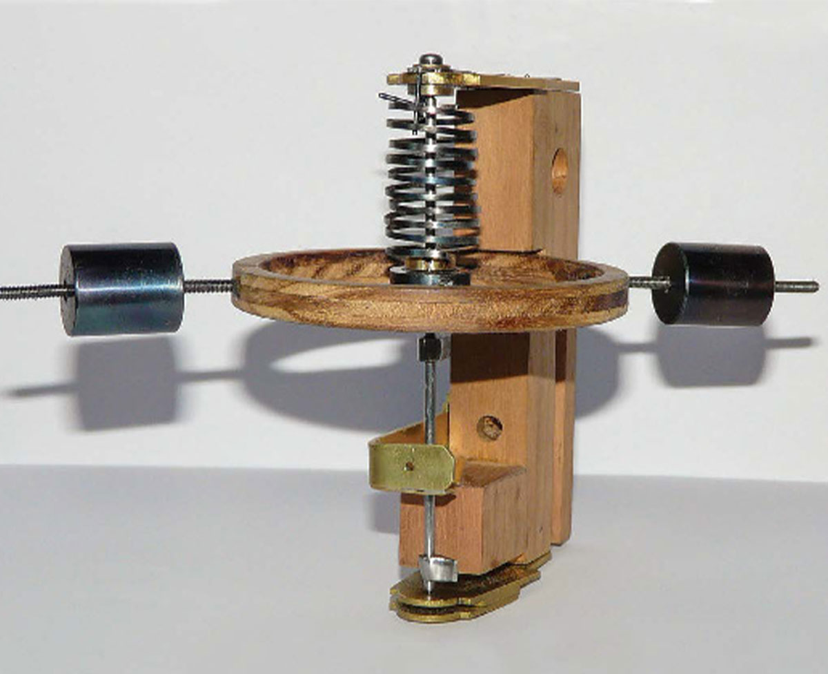
The pinwheel was made from 7.5 mm (0.3") Australian blackwood, three-ply. Twenty-seven pins of 1.25-mm (0.05")–diameter high-carbon steel were evenly spaced around the wheel. Particular care was taken to ensure that the pins were accurately spaced, secure, and of even height. A helical spring measuring approximately 2 cm (0.8") in diameter and 3.5 cm (1.4") in height was made from a piece of 0.3-mm (0.012")–thick clock spring. The clock spring was softened by heating it to cherry red and then slowly withdrawing it from the flame. A strip of approximately 1.6 mm (0.063") × 60 cm (23.6") was cut from the edge of the spring with tin-snips. The strip was then gauged to a 1.5 mm (0.059") width by careful filing until it just passed through a short piece of 1.5-mm–diameter brass tubing. After gauging, the spring was evenly coiled around a piece of 2-cm (0.8")–diameter brass tubing with the ends held in place by hooking them into holes that had been drilled in the tubing. The tube and spring were then heated until the spring was cherry red and hardened by quenching in oil. Verge pallets were next made from tool steel and heat-hardened (Figure 4).

Close-up of a wooden wheel with pins inside of the clock
Figure 4. Top pallet engaging on the pinwheel.

Testing the Escapement and Finding a Problem

Preliminary testing of the escapement was done using small lead weights that could be moved along a temporary wooden bar that oscillated back and forth (Figure 5). Power to the movement was from a can of scrap metal that was suspended by a cord wound around a temporary wooden drum attached to the arbor of the great wheel. The preliminary testing was encouraging; by adjusting the position of the weights on the bar, a beat time near what was needed was achieved. Nevertheless, a pallet would occasionally skip or catch on a pin, but I believed that these were minor problems that could be corrected later. Therefore, I made a balance wheel with two approximately 45 g (1.6 oz) steel timing weights that could be adjusted by screwing them in and out (Figure 6). The fixture was then installed and further testing was done. However, it became apparent that the problem of a pallet skipping or catching was far more difficult to solve than I had imagined. This led to 10 weeks of tantalizing frustration, always so near but so far, and never the eureka moment!

I made numerous adjustments, including slight alterations to the heights of the pins that were either catching or skipping, and changing the geometry of the pallet angles from 60 degrees to 50 degrees and then to 63 degrees. Two weaker helical springs were also made and tested but without success. I found the escapement to be extremely sensitive and unforgiving. Some of the problem may have been caused through minuscule variations in the speed of the pinwheel as it moved from one pin to the next, and/or tiny changes in the oscillation frequency of the balance wheel, but I am still unsure of the precise reason for the pallets to skip or catch occasionally.

An unfinished case of a clock with gears exposed
Figure 5. Preliminary testing of the escapement.
A wooden balance wheel with metal springs and timing weights
Figure 6. Helical spring, balance wheel, and timing weights fixture.

A Compromise That Saved the Project

Because I had invested so much time and effort into the clock, I began to think about how I could save the project. I realized that I could make a recoil escapement and use a pendulum that beats 108 times each minute. Also, by using a 54-tooth escape wheel it would turn once every minute and the arbor could carry a second hand—just as I had planned for the pinwheel. The next questions were, “Would the escape wheel fit into the movement, and was the back plate long enough to accommodate the pendulum?”

First, I calculated the theoretical length of the pendulum required to be about 30.65 cm (12.08"). The procedure for calculating simple pendulum lengths is given by de Carle.4 I also found that the maximum diameter of the 54-tooth escape wheel that could be fitted into the movement was 65 mm. The tooth spacing on the escape wheel was calculated as follows:

65 × π/54 mm = 3.78 mm (0.149")

A black painted finished clock case with pendulum and gears exposed
Figure 7. Completed and installed escape wheel, anchor, and pendulum. Note the two small extensions to the tops of the front and back plates (compare with Figure 5).

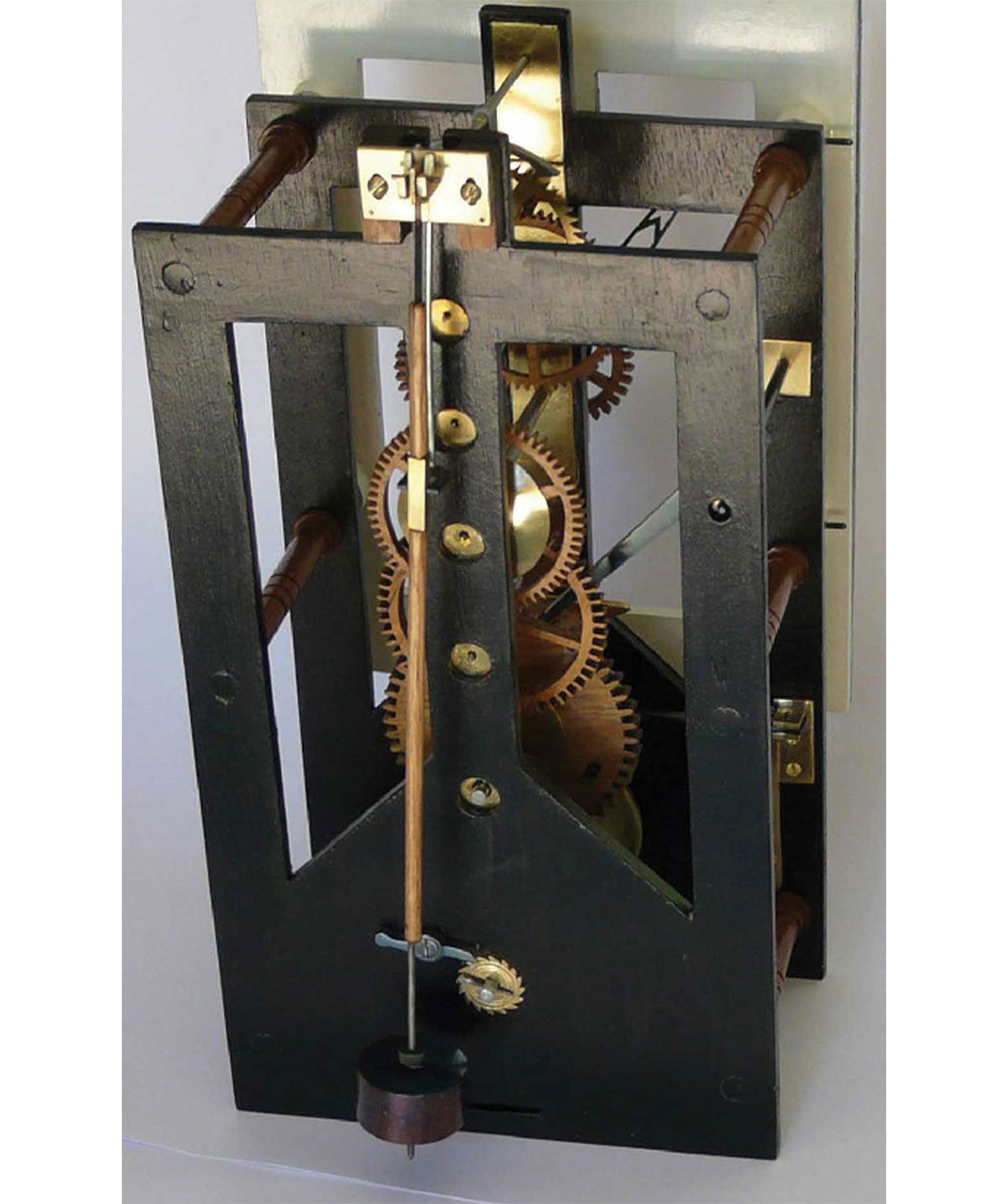
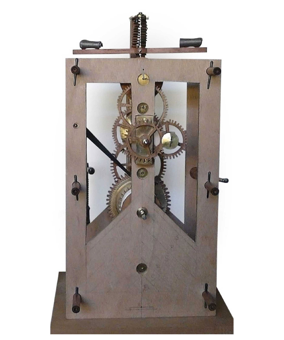
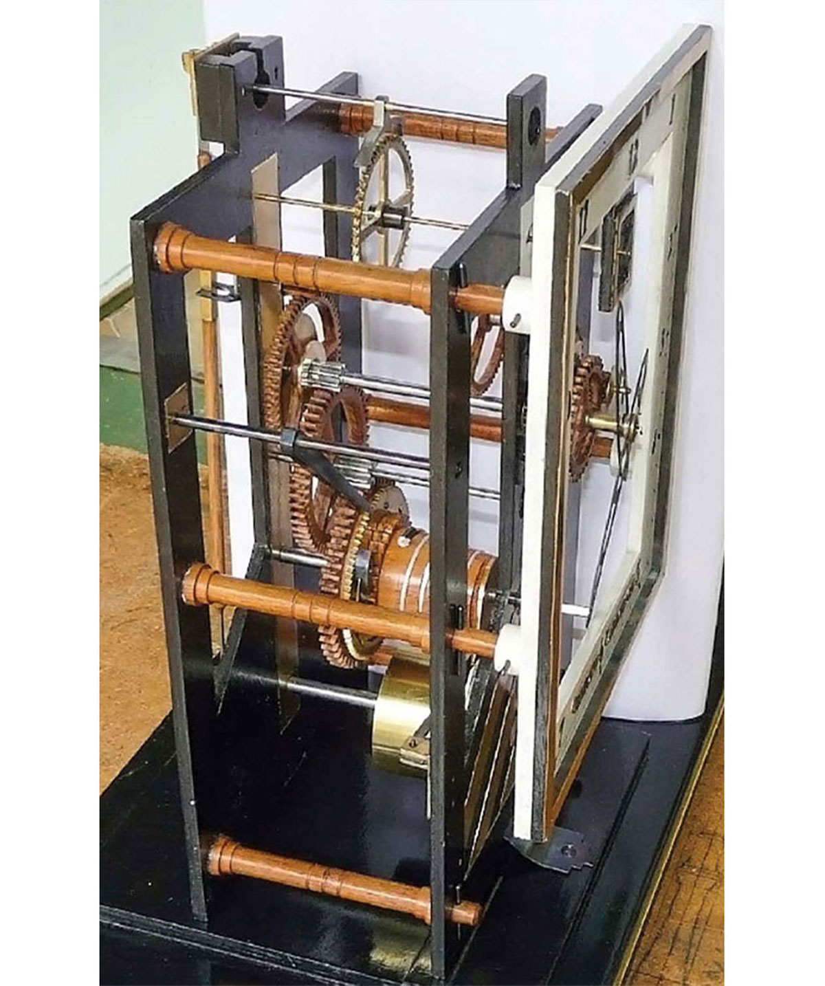
By dovetailing two 4.5 cm (1.8") extensions into the tops of the front and back plates, room was made for the pivot holes for the anchor escapement and the pendulum suspension cock. An anchor escapement was made from an old flat file that was about 4 mm (0.16") thick. The procedures for making the anchor were as those given by Penman.3 Figure 7 shows the completed and installed escape wheel, anchor, and pendulum.

The anchor spans 9.5 teeth on the escape wheel, and the pendulum swings in a full arc of approximately 3.75 degrees. A piece of 0.002"-thick feeler gauge was used to make the pendulum suspension spring, and the bob is of heat-blued steel measuring 38 mm (1.5") (D) × 21 mm (0.83") (H).

The bob weighs 198 g (7 oz) and is drilled through the center so that it can move up and down on a screw thread; it is clamped in place with nuts at the top and bottom. The crutch fork engages on a piece of square brass tubing set into the wood pendulum rod (Figure 8).

After the clock had been adjusted to an accuracy of about 10 sec/day, the length of the pendulum from the flexure point on the suspension spring to the center of the bob was approximately 31.8 cm (12.52"), which was 11.5 mm (0.45") longer than the length I had calculated for a simple pendulum. This difference exists because my pendulum is a compound pendulum and its center of oscillation is above the center of the bob, as is the case with all normal clock pendulums.4

Close-up view of the 54-tooth escape wheel, anchor, and crutch fork
Figure 8. Close-up view of the 54-tooth escape wheel, anchor, and crutch fork.
Unfinished clock up on a shelf with a metal weight hanging below
Figure 9. Setup used to carry out experimental torque tests on the clock main spring.
Close-up of the inside of a clock case on a work shelf
Figure 10. Torque tests were done by winding the square on the spring barrel arbor with a spanner.
Black and white graph with torque inch-pounds on y-axis and number of spring barrel turns on x-axis
Figure 11. Graph showing that the torque delivered by the clock spring is lower when the spring is unwinding than when it is being wound.

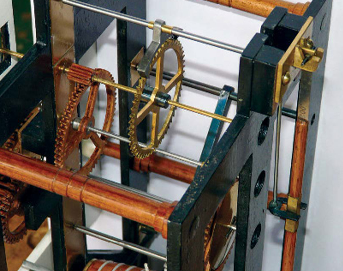
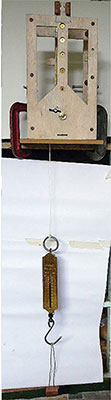
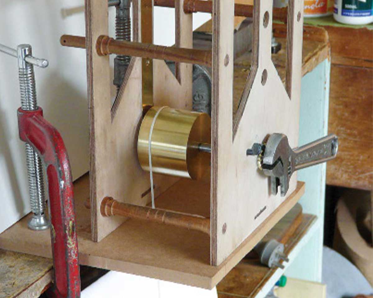
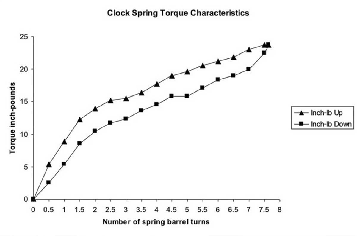
Table 1. Approximate actual torque at each turn of the fusee
Fusee turn 1 2 3 4 5
Torque (inch-lb) 12.4 12.8 13.2 13.3 13.2

Table 2. Gear train details
Item Teeth count Outside diameter (mm/in) Time per turn
Spring barrel 63.3 / 2.49 67.5 hr
Fusee cone 35.8 / 1.41–46.1/1.81 40.5 hr
Great wheel 48 @91.1 / 3.59 40.5 hr
Intermediate wheel pinion (steel) 54
8
79.8 / 3.14
15.8 / 0.62
6.75 hr
Center wheel pinion (steel) 64
8
73.8 / 2.91
12.5 / 0.49
1 hr
Fourth wheel pinion 60
8
67.4 / 2.65
9.9 / 0.39
7.5 min
Escape wheel (brass) pinion 54
8
65.0 / 2.56
9.7 / 0.38
1 min
Cannon pinion 12
17.0 / 0.67 1 hr
Motion wheel pinion 36
8
50.6 / 1.99
13.8 / 0.54
3 hr
Hour wheel 32 53.8 / 2.12 12 hr

I used the temporary wooden drum, which I had attached to the great wheel arbor, to find the drive torque needed to run the clock. This arbor now carries the fusee cone. The drive torque was found by adjusting the weight of a can of scrap metal suspended on a line attached to the winding drum. These tests showed that the clock required a torque of 12 in-lb. Calculations were done to determine the strength of the spring required to deliver sufficient torque.

I bought a spring with the following measurements:

38 mm (1.5") (H) × 0.45 mm (0.018") (T) × 200 cm (78.7") (L)

I calculated its maximum torque to be about 25 in-lb.5 I fitted the oiled spring into a brass barrel with a 56.5 mm (2.22") internal diameter and ran some experimental torque tests (Figures 9 and 10). The tests were done as described in a previous NAWCC Bulletin.6 I found that there were 7.6 turns of the barrel from unwound to fully wound. Tests were done twice, and the mean torque at each half turn of the barrel was calculated. The results revealed significant amounts of hysteresis, with a marked difference in the amount of torque delivered as the spring was wound up and let down (Figure 11). The torque was lower when the spring was unwinding than when it was being wound up. The down curve is the one that actually delivers power to the clock, so I used the section of the down curve between four and seven spring barrel turns.

Using some arithmetic, regression analysis, and experimentation I arrived at the required shape of the fusee cone. The cone is a straight-sided frustum 38 mm (1.5") long with a diameter of 35.8 mm (1.41") at the smaller end and 46.1 mm (1.81") at the larger end. The diameters make allowance for a 2-mm (0.08") groove to hold the fusee line. By using a thread pitch of 7.6 mm (0.3"), I achieved five turns of the fusee to three turns of the spring barrel. The approximate actual torque at each turn of the fusee is shown in Table 1. The fusee turns once every 40.5 hours, and the total running time for the clock is 8.4 days. Figure 12 shows the spring barrel and fusee.

The clock has Harrison maintaining power provided by a piece of 2-mm spring steel wire set in a recess in the great wheel similar to that shown in the August 2001 NAWCC Bulletin.7

Gear train details are given in Table 2.

Finishing the Movement

To give the movement an Art Deco appearance, strips of brass and blued steel were inlaid in a chevron pattern into the bottom section of the front plate. The brass was polished and lacquered, and the steel polished and heat blued. Ultra clear epoxy adhesive was used to hold the strips in place.

The plates were sanded and painted with white acrylic undercoat. After additional sanding, they were painted with a 1:1 mixture of Jo Sonja’s carbon black and Prussian blue hue artist’s acrylic paint. They were then sealed with Jo Sonja’s polyurethane water-based gloss varnish.

Shellac was used to finish the pillars and fusee cone. The wheels were given a light coating of bees’ wax furniture polish using a small brush in a Dremel rotary tool.

View of movement showing the spring barrel, fusee, brass maintaining power wheel, and steel maintaining power detent
Figure 12. View of movement showing the spring barrel, fusee, brass maintaining power wheel, and steel maintaining power detent.

Dial and Hands

The skeletonized dial was made from 6 mm (¼") commercial plywood. It was prepared in the same way as the plates and then painted with warm white artist’s acrylic paint before being sealed with polyurethane water-based gloss varnish. A raised border of polished and lacquered brass was applied to the dial, and the ink lines were done with carbon black Liquitex acrylic ink. Numbers and letters were computer-printed and glued onto a piece of 0.3-mm (0.012")–thick steel with woodworking glue and then cut out with a piecing saw (Figure 13). The paper was removed before polishing and heat bluing. Ultra clear epoxy adhesive was used to hold the numbers and letters in place.

The seconds dial was made from a piece of thin brass and engraved with lines at the 15, 30, 45, and 60 seconds positions. Epoxy adhesive mixed with black oxide powder was used to fill the lines. After the adhesive hardened, the excess was sanded off and the brass polished and lacquered.

Patterns for the hands were drawn on paper and then glued onto a piece of an old 0.8-mm (0.03")–thick bandsaw blade and cut out with a piecing saw. Needle files were used for finishing, and the hands were polished and heat blued. Because the skeletonized hands were difficult to read, they were later backed with thin pieces of brass that were painted with warm white artist’s acrylic paint before being sealed with polyurethane water-based gloss varnish (see Figure 13 and Figure 15). The brass backing pieces were glued in place with ultra clear epoxy adhesive.

View of the dial, hands, seconds dial, and the chevron decoration of brass and blued steel on the front plate
Figure 13.. View of the dial, hands, seconds dial, and the chevron decoration of brass and blued steel on the front plate.
Hand-drawn color illustration of the finished version of the clock
Figure 14. Rough sketch of the clock.

Case

Knot-free pine (Pinus radiata) was used, and the 2-mm (0.08")–thick glass panels were supplied and cut by a local glass works. The case design evolved from a rough sketch of the clock followed by full-size working drawings (Figures 14 and 15). Case dimensions are shown in Table 3.

I used the following steps to finish the case:

  • Sanded with 80, 120, 240, and 400 grit paper.
  • Raised grain with a damp foam brush.
  • Sanded with 400 and 1200 grit wet and dry paper.
  • Sealed with a 1:1 mixture of Jo Sonja’s All Purpose Sealer and Clear Glaze Medium applied with a foam brush.
  • Applied three coats of a 1:1 mixture of carbon black and Prussian blue hue artist’s acrylic paint; the recessed panels were painted with warm white.
  • Applied one coat of Clear Glaze Medium with a foam brush.
  • Sanded very lightly with 1200 grit wet and dry paper.
  • Applied eight coats of Jo Sonja’s polyurethane water-based gloss varnish with a foam brush.
  • Lacquered 2.5-mm (0.1")–diameter brass rods and then glued around the edges of the recessed panels with ultra clear epoxy adhesive.
  • Applied three coats of bees’ wax furniture polish.
Pine clock case before finishing adorned with finished elephants and mouse
Figure 15. The pine case before finishing; the doorknob is of blued steel. Note how difficult it is to see the skeletonized hands before the white backing pieces were applied.

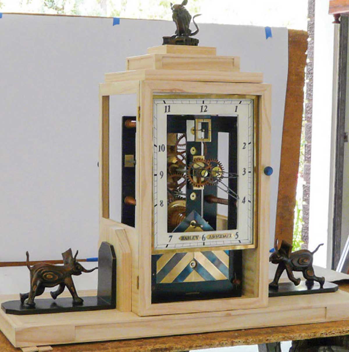
Table 3. Case dimensions
Centimeters Inches
Overall height 63.5 25
    Base
    Width 69.5 27.4
    Depth 28 11
Central tower section
    Height 48 18.9
    Width 25 9.8
    Depth 25 9.8

Figure 16 shows the case before vanishing and applying the brass rods around the recessed panels.

Bronze Garnitures

The case is decorated with a mouse and two baby elephant bronze garnitures. The mouse sits in a shallow recess at the top of the central tower, nibbling on a piece of cheese while the two elephants charge at the base. The mouse was inspired by the nursery rhyme “Hickory Dickory Dock.” Legend has it that the nursery rhyme had its origin from the astronomical clock in Exeter Cathedral in Devon, UK. It is said that mice would climb up into the clock to nibble the fat used to lubricate the movement and that, in the 17th century, a bishop cut a hole in a door below the dial so that his cat could get in to chase the mice.8 There is also a very old but unsubstantiated belief that elephants are afraid of mice.

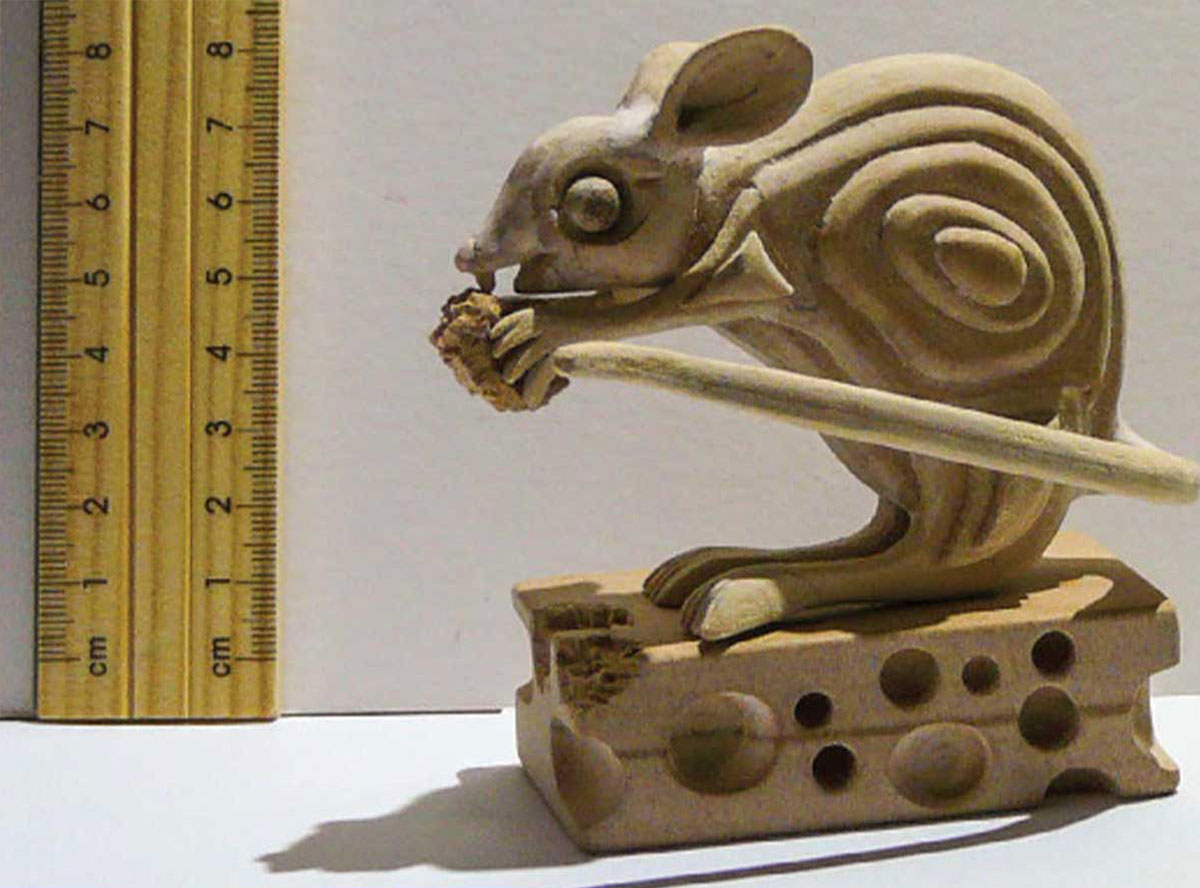
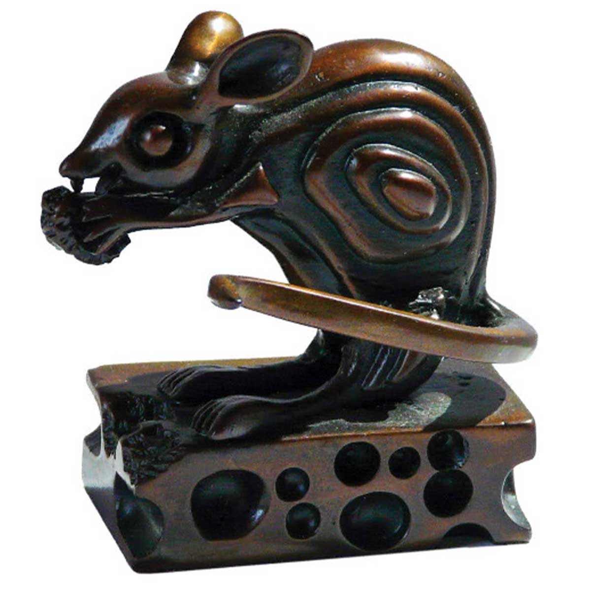
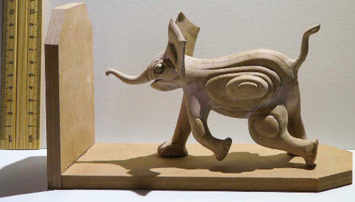
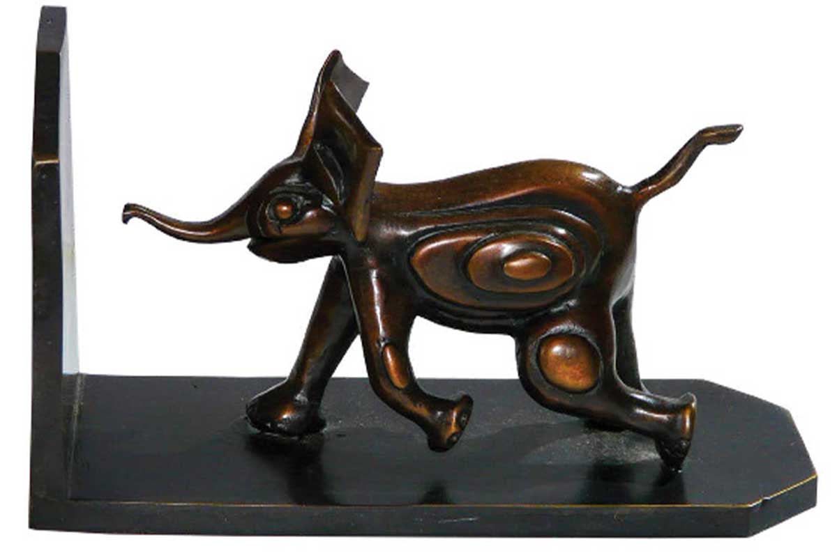
I made stylized contour relief models of the mouse and baby elephants by laminating pieces of medium-density fiberboard glued together with wood-working glue (Figure 17). The models were sent to a specialist art foundry for casting and patinating. The lost-wax method of casting was used, which achieved excellent detail in the finished bronzes (Figure 18).9 The two elephants were cast from the same fiberboard model.

Concluding Remarks

Although I was unsuccessful in making the verge and balance wheel escapement as I had planned, through careful thought I was able to find a compromise that saved my clock. In addition, I was reminded of how challenging and rewarding clock-making can be, and this is one of the reasons why I find it so fascinating. The clock runs well and keeps time to about a minute per week, which is probably much better than would have been possible with the verge and balance wheel escapement, had I been successful in making it.

Clock case before varnish
Figure 16. The case before it was varnished and the brass rods applied around the recessed white panels.

Notes and References

  1. Throughout this project I worked in millimeters. Where inches are given, they have been calculated using 25.4 mm = 1 inch.
  2. Bailey DR. Willard-style timepiece with a wood movement. Watch & Clock Bulletin 2016;419(Jan/Feb):69–80.
  3. Penman P. The Clock Repairer’s Handbook. Devon, UK: David & Charles Publishers, 2000.
  4. de Carle D. Practical Clock Repairing. London: N.A.G. Press, 1982.
  5. Rawlings AL, Treffry T, Treffry A. The Science of Clocks and Watches. London: Longman and the British Horological Institute, 1993.
  6. Bailey D. A spring-driven wooden wheel skeleton clock. NAWCC Bulletin 2009;379(April):137–140.
  7. Bailey DR. Effects of humidity and temperature on the performance of a wooden clock. NAWCC Bulletin 2001;333(Aug):475–487.
  8. Conolly P. Exeter Cathedral’s curiosities. Accessed November 18, 2019. www.tinyurl.com/w8cnme7.
  9. The bronze garnitures were cast and patinated by Crawford’s Casting, Sydney, NSW, Australia.

About the Author

David Bailey has been an NAWCC member since 1991. This is his eighth Watch & Clock Bulletin article. He studied agricultural science at the University of New Zealand and the University of Queensland. Bailey has authored more than 40 papers and articles in the fields of agronomy and computerized farm planning. He is an octogenarian and his interests include wooden-wheel clock-making, wood-working, genealogy, and folk art painting.

Fiberboard model of the unfinished mouse
Fiberboard model of the finished bronzed mouse
Figure 17. (A and B). Medium-density fiberboard models of the mouse and baby elephant.
Fiberboard model of the unfinished baby elephant
Fiberboard model of the finished bronzed baby elephant
Figure 18. (A and B). The finished bronzes.
Watch Blog
Most Read
About Us